Additional Material for Section 2.1
This "construction" will start with all the collection of nodes in a ugraph. Then it will proceed by adding edges to it from some list of edges. This may be done in a drawing if the ugraph is not to big and complicated. But it could be done by computation. If the ugraph is small then the work can be done by hand, as shown below. Otherwise the computer could do the work by executing some program.
Addition of edges provides the action. Attention is focused on the components. There are two possibilities.
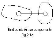
(A) The edge being added has end points in different components. The edge becomes a "bridge" between those components so they are no longer separate components. They become one bigger component. The number of components decreases by one.
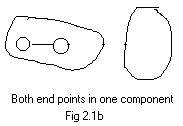
(B) The edge being added has end points in the same component. Then is no change in the components. However, this happens if the added edge completes a loop. This loop will be in the final ugraph, after all the edges in the list have been added.
If a component has nodes X,Y,Z in it, then X is a node in [X], Y is a node in [X], and Z is a node in [X]. ([Y] or [Z] could be used in place of [X].) This can be written more briefly as a table:
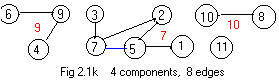
node 1 2 3 4 5 6 7 8 9 10 11
comp 7 7 7 9 7 9 7 10 9 10 11
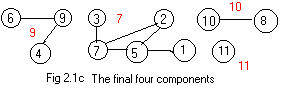
[7], [9], [10], [11] denote the final components.
The list of edges is:
 There are eleven nodes in the ugraph. The process starts with the table
node 1 2 3 4 5 6 7 8 9 10
There are eleven nodes in the ugraph. The process starts with the table
node 1 2 3 4 5 6 7 8 9 10
comp 1 2 3 4 5 6 7 8 9 10
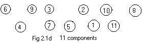
Fig 21d shows a labeled ugraph of 11 isolated nodes. The table says equivalently that each node is its own component. Each component has just one node in it.
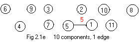
Add the first edge 1-5 in list (#). The table and figure (Adm 2.1e) become
node 1 2 3 4 5 6 7 8 9 10
comp 5 2 3 4 5 6 7 8 9 10
In Fig 2.1e a new component [5] has been formed. Notice that under 1 and 5 in the table the component name 5 appears. The table says that nodes 1 and 5 are in component [5].
The rule for adding an edge X-Y:nbsp; Look directly under the nodes X and Y. Replace all appearances of the component number under X by the component number under Y.
The component number under 1 is replaced by the component number under 5. So 5 is placed under the node number 1.
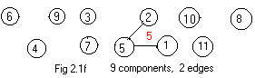
The addition of the next edge 2-5 in list (#) creates a new component which is called [5] also.
 node 1 2 3 4 5 6 7 8 9 10
comp 5 5 3 4 5 6 7 8 9 10
The component numnber under node 2 has been replaced by the component number under 5, which is 5 The new component in Fig 2.1f has the name 5,
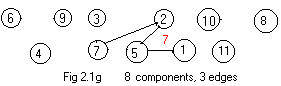
The thrid edge 2-7 in list (#) is added to produce a table and Fig 2.1g:
 node 1 2 3 4 5 6 7 8 9 10
comp 7 7 3 4 7 6 7 8 9 10
In this case all the 5's (there was a 5 under the node 2 in the previous table) have been replaced by the 7.
In the list (#) the left end point of each edge is less than the right end point. This will cause replacements in the tables of smaller component numbers by larger component numbers. This fact can be used to check the derivation of any table from the previous table.
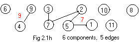 The additions of edges 3-7 and 4-9 produce the table and Fig 2.1h:
node 1 2 3 4 5 6 7 8 9 10
comp 7 7 7 9 7 6 7 8 9 10
The addition of the next edge 5-7 is special.
 The numbers under nodes 5 and 7 are equal, namely 7. The current table
node 1 2 3 4 5 6 7 8 9 10
The numbers under nodes 5 and 7 are equal, namely 7. The current table
node 1 2 3 4 5 6 7 8 9 10
comp 7 7 7 9 7 6 7 8 9 10
is the same as the previous table, because 7 under 7 replacing 7 under 5 makes no change. But looking at Fig 2.1j the addition of edge 5-7 has made a loop 2-5-7-2. For that reason a special color blue is used to show edge 5-7 in the drawing of the ugraph in Fig 2.1j.
. The loop is part of the component [7].
 Additions of edges 6-9 and 8-10 produce the table and Fig 2.1k:
node 1 2 3 4 5 6 7 8 9 10
comp 7 7 7 9 7 9 7 10 9 10
The "edges" 8-0 and 0-0 in (#) are not real edges. They do not change the table nor the drawing, except to add a red 11 near the node 11. See Fig 2.1c.
Using blue to denote the special edge that makes a loop, list (#) becomes
Loops in ugraphs and edges that complete loops will be discussed again in sections 2.2 and 2.3 in Chapter 2.
In some ugraphs a certain node or a certain edge plays an essential role in the "wholeness" of a component. Its deletion "breaks" the component into two or more parts. Each of those parts is itself a component.
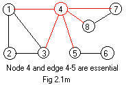
If a node is deleted then all edges touching that node must be deleted. No edge can be left "hanging" without an end point. If node 4 in Fig 2.1m is deleted (and all red edges also deleted) then the ugraph will have 3 components: 1,2,3, 5,6, 7,8. Node 4 is called an articulation point in the general literature. But nodes 2,6,7 may be deleted and the ugraph still "hangs together" without these nodes. Therefore, none of nodes 2,6,7 are articulation points.
In some situations uninteresting isolated nodes are temporarly deleted or ignored, the ugraph is processed and later those isolated nodes are restored to preserve the number of nodes.
If an edge is deleted its end points still stay in the drawing. Sometimes one or more nodes become isolated. In any case the deletion of an edge never changes the number of nodes. If edge 4-5 is deleted from the ugraph in Fig 2.1k then there are two components: 1,2,3,4,7,8, 5,6. The edge 4-5 is called a bridge The edges 1-3 and 7-8 are not bridges, because they are parts of loops. But edge 5-6 is another bridge.
Return to main text: top / section 2.1
===============
Additional Material for Section 2.2
filler
filler
filler
Return to main text: top / section 2.2
======
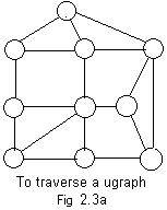 There is an interesting problem whose solution can be solved by traversing a realistic ugraph. A detective must examine completely all the rooms of a house of rooms and corridors for evidence. The plan of the house is shown in Fig 2.3a. However the detective is not given this plan. And he knows that the search of each room requires much time. Therefore, he does not want to search any room more than once.
The house plan has many loops. If he is not careful the detective could waste much time searching the same rooms two or more times by moving along some loop two or more times. (It would be convenient if he were shown a spanning tree, but he does not have this advantage.)
To avoid moving into the same room twice, he rips up some paper and leaves a piece of that paper in every room that he has visited. Then at any room he looks down each corridor to see if it has a piece of paper or not. He selects a corridor to a room without paper.
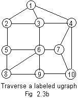 The contractor who built the house assigned a unique integer label to each room which is visible from every adjacent rooms. See Fig 2.3b. (The door to the house leads to the room with the number 1.) This will allow the detective to record his various paths and make sure that he has visited all of the rooms. Suppose he records the chain
When the detective is in room 2, he can choose adjacent rooms 3 or 5. He chooses the room with the smallest acceptable number every time. (He cannot choose 1.) This choice of the room with the smallest acceptable number provides a method for deciding which corridor to traverse.
This chain (converted to undirected edges) fits the definition of a spanning tree. It is a tree with a long trunk and no branches. More importantly it has no loops and contains all the nodes (rooms).
The above chain (tree) can also be derived from the adjacency array for the labeled ugraph shown in figure Adm 2.3b.
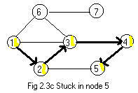 More often the method of traversing a connected ugraph does not produce a single chain of nodes, i.e. a tree without branches. A modification of the method given above is needed to produce any necessary branches of the tree. Branches happen when the detective in some room cannot go to an unvisited adjacent room, yet not all the rooms have not been visited. This happens while traversing the ugraph shown in Fig 2.3c.
Starting at room 1 (this means that the detective enters the house at room 1) he then traverses a path 1 -> 2 -> 3 -> 4 -> 5 by selecting the next room each time with the lowest number. This leaves him in room 5. He cannot go on to room 2 because he (sees a yellow piece of paper and knows that he) has already visited that room. Yet he has not been in rooms 6 and 7.
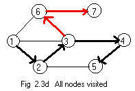
To solve this dilemma he backs up (back-tracking) through rooms that he has previously visited until he is in a room with another way out (another corridor to a room without a piece of paper). He backs up to room 4. There he cannot find a way out because he has already visited room 5. He backs up again to room 3. Now he has another way out, a corridor to room 6. Then he continues on to room 7. All rooms have been visited. Fig 2.3d shows a directed tree containing all seven nodes.
It should be noticed that back-tracking on a path requires the path to be directed. Back-tracking must go in a direction opposite to the arrows along edges. Back tracking allows a motion to a node previously visited.

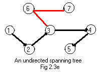 Fig 2.3e shows the spanning tree created by the transversing of the ugraph. Fig 2.3f shows an equivalent tree in the usual position for graphs that are trees.
Now the detective is stuck in the last room 7 (assume only room 1 has a door to the outside). He can use the method of back-tracking to find that exit from the house. Using the directed paths in Fig 2.3d he can back track to room 3 along (red) arcs . There is only one directed path into room 3. It is a (black) arc from room 2. Therefore he backtracks to room 2 (and not from room 3 into room 4 - that would not be back tracking). Finally he is again in room 1 and can now make an exit from there.
Return to main text: top / section 2.3