Suppose x is already in the tree.
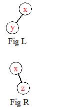
The basic idea is how a number from the sequence is inserted into the tree after a number already in the tree.
Suppose x is already in the tree.
A specific example will illustrate the construction.numbers shortly. For a number y
After a node is placed, a link joins it to its parent node.
Given the following sequence of eight numbers
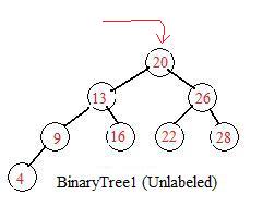 The first number (20) of the sequence always serves as the root. Through it all the remaining numbers flow into the tree their nodes become attached.
The next number 26 enters at the root. Since 26>20 the node containing 26 is placed to the lower right of the node containing 20.
The next number 13 enters at the root. Since 13<20 the node containing 13 is placed to the lower left of the node containing 20.
The next number 9 enters at the root. Since 9<20 the node containing 9 goes to the lower left and meets the node containing 13. But since 9<13 it is placed the lower left of the node containing 13.
The next number 28 enters at the root and goes past the node containing 26 and is placed at the lower right of 26.
Similarly nodes containing 16,4,22 enter at the root and proceed down to be placed in the tree.
Node containing 16 goes to the lower right of the node containing 13 and is placed there.
Node containing 4 goes to the lower left of the node containing 13
and is placed there.
Node containing 22 goes to the lower left of the node containing 26
and is placed there.
The binary tree has been constructed from the given sequence and its nodes contain all of the numbers.
The computer does not use BinaryTree1 with values written on the nodes.
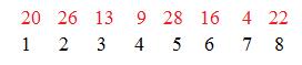 For a graph of 8 nodes the first eight natural numbers should serve as labels. To get these, as numbers are taken from the sequence, the computer is counting them and attaching these counting numbers on the nodes, where they become legitimate labels. In BinaryTree2 the values from the sequence are "written" near the nodes to which they are associated.
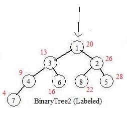
The computer uses the equivalent of BinaryTree2 without the values assigned to the nodes. It follows a definite search pattern determined from the way that the tree was constructed. For example the smallest number is found by entering the tree at the root and going down all the left links until the leaf. The number 7 is the label. The computer locates the seventh number in the sequence, and prints out 4. The computer continues following the pattern and finds the nodes with labels
The given program will accept sequences in which the numbers have repetitions. And the program can be modified to accept any finite sequence of real numbers, but the same pattern may be used.
For the computer sorting using binary trees click here and then click on application file BinaryTreeSort.
 (1),2,3,4, #4,5,2
All numbers after ), to end of line are neighbors and weights copied from the graph. However, the spaces before # are not necessary.
The computer controls a robotic bug . It directs the bug to visit all the nodes in a connected Ugraph. There must be a first node which marks the start of the journey of the bug about the graph, and a last node when the bug has finished the task.
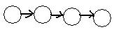 During the journey the bug most often enters a node from some link and goes out of that node along a different link. The task is simple for traversing all the nodes in the linear graph in the adjacent figure from left to right.
The journey is more complicated if some nodes have more than one way out (degree 3 or higher). In each of those nodes a decision must be made: which exit to select. In the chapter 4 the computer will use numbers assigned to all the links to be used for the choice of exits from nodes. In this discussion the numerical labels assigned to each node will be used. In the full adjacency array a list of all of its adjacenct neighbors after each (node). The following method can be used: when the bug is in a node with more than one exit, the computer which sees only (the equivalent to) the long adjacency array selects the neighbor with the lowest label number and the bug exits along the link that leads to that neighbor.
Three common problems arise and additional parts will be added to this method to produce a universal solution:
(a) while trying to visit all nodes the bug may visit some nodes more than once;
(b) by choosing every time a neighbor with the smallest label number the bug may traverse an endless loop;
(c) after moving along a path through nodes, the bug may enter a node with no other way out.
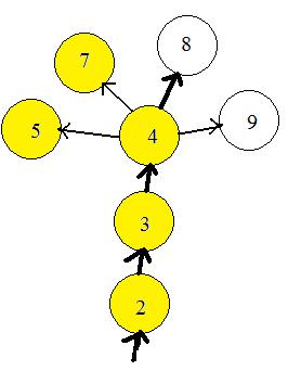 The computer can prevent the bug from entering any node more than once, by remembering what nodes have been visited. It puts a mark by the label number if the node has been visited. In the adjacent figure the nodes already visited are colored yellow. The computer bug has already visited nodes 5 and 7 during travels in another part of the graph (not shown).The bug has moved along through nodes 2 and 3 and has entered node 4, coloring the nodes as it enters. The unvisited neighbor of node 4 with the lowest number label is nod 8. The bug exits node 4 and goes to 8. Then node 8 will become yellow. The computer will actually put a mark by label 8. The avoiding of nodes already visited solves problems (a) and (b).
There are two types of nodes with no exits: (1)a leaf (node of degree 1) has an entrance but no exit, and (2) all the neighbors of a node have already been visited. Both problems are solved by allowing the bug to back up until it finds a node with one or more unvisted neighbors. Therefore, a bug must allowed to back up into a visited node, but not go forward into a visited node. With this agreement, no node will be visited more than once.
This backing up procedure has a problem. When the bug is in the last node, then all nodes have been visited. Backing up will take the bug all the way back to the first node where it entered the graph. The computer cleverly created an "artificial node" not part of the graph, and assigned it the prohibited number label 0 (zero). The artificial node is linked artificially with the first node where the bug entered the graph. Since all nodes of the graph have been visited, the bug in the first node will back up into the artificial node. The computer detects the label 0 and terminates the program.
The computer may list all the visited nodes. The list should be a permutation of all the label numbers, that is, a permutation of 1,2,...,n, where n = number of nodes.
Two comments should be made. The choice of the neighbor of a (node) with the smallest label number may be changed to the choice of the neighbor that has not yet been visited and has the largest label number. The printout of all the visited nodes will be another permutation of 1,2,...,n. Other systematic selections of neighbors will produce new permutations.
The above procedure of a travelling bug can be extended to Ugraphs that are not connected. After the bug has visited all nodes in a component it backs up into the zero node, the computer checks to see if any node in the graph has not yet been visited. If any exist it selects the unvisited node with the smallest label number, attaches the zero node to it and the bug enters that node. By this method all the nodes of the graph will be visited. More useful is the printing out all the nodes in each component separately. In this way the computer reveals all the components of the graph.

The problem of the red player was given to students studying computer programming: they were to create a program that would accept numbers from a person, and the computer would choose the right numbers to win. For the computer to be always the winner, a strategy is needed, and a convienent method to develop it is the above graph, which is "almost" a tree.
Note: the accumulating sums are included inside the circles. So the numbers there are not labels.
The above diagram shows a division into three trees, if the person first chooses 1,2, or 3. Suppose he chooses 2. The central tree shows that the computer chooses 1. The accumulating sum 3 is inside the circle.
Then the person may choose either 2 or 3. If he choose 2 then the accumulating sum is 5 and the computer chooses 3 and the accumulating sum is 8. The computer wins (CW).
But if the person chooses 3 then the accumulating sum is 6 and the computer chooses 2 making the accumulating sum 8. So the computer wins that way also.
The reader may trace through the other trees where the person has chosen 1 or 3. Notice that the computer wins if the person is forced to choose numbers that make the accumulating sum larger than 8.
The reader is invited to run the program "Game of 8" by clicking here and lose every play.
AB,BC AB,BD AB,DA AB,EA AC,BD, AC,DA AC,DB AC,EA AC,EB AD,EA AD,EB AD,EC
BC,AB BC,DB BC,EB BD,AB BD,AC BD,DA BD,EB BD,EC
DA,AB DA,AC DA,BD DA,EB DA,EC DB,AC DB,BC DB,EC
EA,AB EA,AC EA,AD EB,AC EB,AD EB,BC EB,BD EB,DA EC,AD EC,BD EC,DA EC,DB
----------------------------------------------------------------------------------------------
Label coding of ways of going through the intersection:
AB 1 AC 2 AD 3 BC 4 BD 5 DA 6 DB 7 EA 8 EB 9 EC 10
---------------------------------------------------------------------------------------------
Associating pairs of ways of going through the intersection with pairs of natural numbers that will become input-data:
1 4 1 5 1 6 1 8 2 5 2 6 2 7 2 8 2 9 3 8 3 9 3 10 AB,BC AB,BD AB,DA AB,EA AC,BD, AC,DA AC,DB AC,EA AC,EB AD,EA AD,EB AD,EC
4 1 4 7 4 9 5 1 5 2 5 6 5 9 5 10 BC,AB BC,DB BC,EB BD,AB BD,AC BD,DA BD,EB BD,EC
6 1 6 2 6 5 6 9 6 10 7 2 7 4 7 10 DA,AB DA,AC DA,BD DA,EB DA,EC DB,AC DB,BC DB,EC
8 1 8 2 8 3 9 2 9 3 9 4 9 7 9 6 10 3 10 5 10 6 10 7
EA,AB EA,AC EA,AD EB,AC EB,AD EB,BC EB,BD EB,DA EC,AD EC,BD EC,DA EC,DB
Short adjacency array is:
(1),4,5,6,8, (2),5,6,7,8,9, (3),8,9,10, (4),7,9, (5),6,9,10, (6),9,10, (7),10, (8), (9), (10)
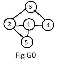
This is all that the computer needs to find compatible collections (equivalence classes) of nodes.
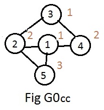
After accepting the input-data the computer will follow a path starting with node 1, passing through nodes 2,3,4 and finishing with node 5. Along the way it assigns a natural number to each node. These numbers are called color codes. The computer tries to assign anumber that has already been used (to use as few color code numbers as possible). If that is not possible it assigned a new number. The resulting graph in theory would appear as in Fig G0cc with the color code numbers attached to the nodes.
The computer prints out the compatible nodes (without their color code numbers) as
Comparing Fig G0cc and Fig G5 on the main page, it is easy to "decode" the color code numbers as follows:
The computer will follow another path starting with node 2 and ending with node 1. Another path starts with node 3, then node 4 and finally node 5. After completing each path the computer prints out the array of compatible objects separated by a slash / and the number of collections (equivalence classes) of compatible objects. For any graph with a very large number of nodes, any of such number usually is larger than the chromatic number (the smallest number of collections).