
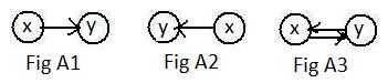
 There are situations that allow motion along links to go in one direction but not in the reverse direction. Vehicles along one-way streets, water flowing naturally through pipes down a hill, and direct current electricity through wires are examples. The notation in drawings for such a situation is shown in the adjacent Fig A1 and Fig A2 with arrows. Motion can go from node x to node y but without any other information, it cannot go from node y back to node x over the same link. These are examples of a directed link from x to y. Also it is an outgoing link from node x and an incoming link to node y. Both x and y are known as endpoints of the directed link. (Recall the terms "tail" and "head" for vectors.) And both of the equivalent notations
In Fig A3, motion can go from either node to the other, like cars on a two-way street. The bi-directional links of the last two chapters may be represented in this chapter by the pair of directed links pointing in opposite directions between the nodes. The nodes are downlink neighbors of each other.
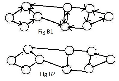
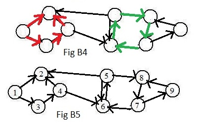
Sometimes it is useful to count the directed links involved with a node. The indegree of a node is the number of incoming links pointing at the node. The outdegree of a node is the number of outgoing links from the node. In Fig A4 the indegree of the node is 3 and the outdegree is 2. If the two outgoing links are removed then the node would have indegree = 3 and outdegree = 0. In this chapter there will be no digraphs with nodes having both indegree = 0 and outdegree = 0, which would mean that the nodes would be isolated.
 [1.1] (digraphs) A graph in which all of the links are directed is called a
Digraph means directed graph.
The type of links determines whether a graph is a digraph or a ugraph. Fig B1 shows an unlabeled digraph with 9 nodes.
Fig B2 shows the same nodes but the links have been replaced by undirected links. This graph is called the corresponding ugraph.
Directed paths play an important role in digraphs. A directed path from node x to node y is a sequence of nodes and directed links satisfying the following:
(a) the number of nodes is finite, and distinct (no repeats);
(b) the first node has only a single outgoing link, and the last node has only an incoming link;
(c) except for those two nodes, each of the remaining (interior) nodes has a single incoming link from the previous node and a single outgoing link to the next node.
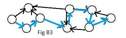 The nodes mentioned in (b) are called start node and finish node respectively. Fig B3 shows a digraph with a directed path from the extreme left node to the extreme right node. It happents that it is the only directed path connecting those two nodes. (Usually there are more directed paths connecting nodes in a digraph.) Any attempt to go along another way will encounter going along some directed link in the wrong direction. Notice that in the corresponding ugraph in Fig B2 there are many paths from the extreme left node to the extreme right node. It is usually more difficult to find a path from one node to another in a digraph than in a ugraph. In general, it is more difficult to work with digraphs than ugraphs.
The term "loop" has a special meaning when directed links are involved.
A directed loop is a sequence of nodes and directed links, satisfying the following conditions:
(a) the number of nodes is finite, and distinct (no repeats);
(b) each of the nodes has a single incoming link from the previous node and a single outgoing link to the next node.
(c) there is a directed link from the last node to the first node of the sequence.
Actually, (b) implies (c). But (c) relates to the definition of a path. A loop is a path in which the start node and the finish node coincide.
Fig B4 shows a green directed loop involving four nodes. Motion may start at any of the nodes and go along the green links to return to the node where the motion started. There is another directed loop to the right involving three links. But the four red directed links do not form a directed loop. The directed link pointing to the upper right points in the "wrong" direction. Although the red links and nodes do not form a directed loop in Fig B4, their counterparts in the corresponding ugraph in Fig B2 do form an undirected loop.
After the nodes in Fig B1 have been given labels the result is shown in Fig B5. The blue path in Fig B3 can now be denoted in the usual notation:
 The six nodes in Fig C have been given labels. What form of input-data does it take to represent this digraph in the computer? The graph is different from its corresponding ugraph, so the input-data must be different. The answer is:
The short adjacency array for digraphs is composed of all the nodes in increasing order in parentheses. After each node are all of its successor neighbors. The numbers on predecessor neighbors are never given near the (nodes) in this array.
The input-data (#) contains the short adjacency array for digraph in Fig C. Like the short adjacency array for ugraphs the total number of successor numbers is equal to the number of directed links in the digraph. However in the short adjacency array for digraphs, the successor neighbors may have smaller numbers than the (nodes).
The fourth cluster (4),1,5, denotes the directed links 4 → 1 and 4 → 5.
Notice that only outgoing links from the (node) are represented in the input-data for a digraph.
Although node 3 has predecessor neighbors 2 and 6, node 3 has no successor neighbors. Hence the node (3) in the adjacency array has no successor neighbors written after it.
For each digraph there is a long adjacency array. It is more readable if it is written as a list. In it the predecessor neighbors are written before each (node) and the successor nodes are written after the (node). For Fig C the list is
                                4,(1),2
                                1,(2),3,5
                              2,6,(3)
                                  (4),1,5
                              2,4,(5),6
                                5,(6),3
Each (node) is printed on a separate line in parentheses. The long adjacency list is more informative about the digraph than the short adjacency array and often the computer prints it out, but never use a long adjacency list or its equivalent as part of the input data for the computer. Use the short adjacency array inside the brackets of the input-dataIn a digraph the directed links usually impose severe restrictions upon motion between nodes. In Fig C, it is impossible to go from node 5 to node 1.
[1.2] (Reachable nodes) In a digraph a second node is reachable from a first node if there is a directed path from the first node to the second.
In Fig C node 6 is reachable from node 1, because there is a directed path: 1→2→5→6. (but node 1 is not reachable from node 6). From node 3 no other node is reachable. Is there a single Hamiltonian path in the entire graph showing that node 3 is reachable from any other node in the digraph?
Click on Computer(ReachableD) and select input-data "Fig C" in file (F) to find what nodes are reachable from each of the nodes 1 and 6 and 3.
 Among the various applications of digraphs one involves the rate of flow of water (or any liquid) through pipes. The wider the pipe, the more water can flow through it. For each pipe there is a maximum flow through it, because the water cannot be compressed. For each link representing a pipe, a number representing the maximum flow through the pipe. Actually it is a rate, the number of gallons of water in a minute (or an hour). This maximum number is a weight assigned to the link. In all discussions here it will be a natural number.
The adjacent Fig E1 shows a digraph, in which the directed links represent pipes and directions of water that flows through them. Outside the digraph are an infinite source S of water and a destination D (also called a sink) which can accept any amout of water. Then the water flows from S to D. (Consider the graph on a hill, and S is higher than D.) Also outside the digraph is a directed link from S to one of the nodes, called the entry node, and a directed link from another node, called the exit node, to D. Summarizing, a flow of water comes from S, enters the digraph at the entry node, flows through the digraph and leaves the digraph at the exit node to go to destination D..
Another interpretation of the digraph is a fleet of trucks receiving identical loads of material (grain, oil, water) at the entry node from the source S, and then carrying the loads through the graph of roads and arrive at the exit node where they dump the loads to D. In this interpretation the weights on the links indicate the maximum number of trucks that can use that link in one hour. In both interpretations the weights on links indicate rates of transfer of material along the links.
The entry and exit nodes are considered special nodes of the digraph. The entry node has the only incoming link from outside the graph but has one or more outgoing links into the rest of the graph. The exit node has the only link pointing outside the graph, and the exit node has no outgoing link that belongs to the graph. All other nodes are called interior nodes. For any interior node to be useful it must have at least one incoming link and at least one outgoing link to allow flow through it. Without any incoming link no water or truck could enter it. Without any outgoing link water would fill it and stop the flow through the link, and trucks would make a traffic jam in it with no way out.
The pipes (directed links) are of various sizes. Each size allows a maximum amount of flow through it
as indicated by the weight attached to the link. They are called capacities of the pipes (links). They restrict the amount of flow that can pass through the digraph from entry node to exit node.
For trucks carrying material the weights indicate the number of trucks that can go through along the roads (links) each hour. Some roads allow more traffic than other roads.
In order for them to represent flow through links, the weighted digraphs in this section satisfy the following conditions:
[2.1] (Transportation networks) A digraph with links with weights is a transportation network if it satisfies the following conditions
(a) It has a finite number of nodes and links.
(b) There are no directed loops.
(c) It contains exactly one entry node and one exit node.
(d) Every interior node is reachable from the entry node, and the exit node is reachable from every interior node.
(e) Assigned to every directed link inside the digraph is a weight that is a positive number.
Condition (d) is very strong. It implies that the exit node is reachable from the entry node. Also it implies that the graph is connected.
In discussions in this chapter most often weights will be natural numbers. (Difficulties may arrise if weights that are decimals or fractions are included in input-data to some programs soon to be discussed.)
 In discussions in this section it will be convenient if the entry node always receives the integer-label 1, and the exit node always receives the largest integer-label (the last and largest natural number assigned to the nodes). For Fig E1 the exit node on the extreme right will receive 6, because there are 6 nodes in the graph. (See Fig E2.)
The following is the input data for Fig E2:
[2.2] (Conventions) For most drawn graphs,
(a) In drawings the entry node will be located more left than any other node, and the exit node more right than any other node.
(b) For labeled digraphs, the entry node will usually be assigned 1, and the exit node n, where n is the number of distinct nodes.
In Fig E1 the digraph satisfies all of the conditions of [2.1] and Fig E2 satisfies conventions of [2.2].
[2.3] (Flow through the graph) The flow from entry node to exit node in a graph of directed links with weights is subject to the following conditions:
(a) The amount of flow through any link cannot be more than the capacity of that link.
(b) There is no loss or increase of material flowing anywhere in the graph (pipes or roads).
 The maximum flow allowed by the graph from entry node to exit node is the main topic of this section. (Assume the weights give maximum flow in cubic feet, liters, or gallons, etc, all using the same units of volume per time.) Obviously, for a flow of 1 into the entry node the graph would allow a flow of 1 from the exit node. Intuition tells us that the graph would allow a greater flow into the entry node. (See Fig E3.) Flow of 2 or 3 would pass through the graph to the exit node without decrease. However, a flow of 10000 into the entry node would not. The water would spill over at the entry node because not all of it could go through the pipes (links).
Experiment shows that the graph allows a flow of 12 into the entry node to go entirely to the exit node without decrease or spill over, but not 13. Any flow greater than 12 at the entry node, causes an overflow at the entry node. Therefore, 12 is the maximum flow through the graph. The simplicity of Fig E3 allows a simple analysis of the weeighted digraph to arrive at this number 12.
Figure E3 shows a graph with two directed paths from entry node 1 to exit node 6. The following statement applies to either path separately:
The maximum flow through a path of several connected pipes (links) is determined by the pipe (link) with the smallest capacity.
For this reason, the upper path in Fig E3 will allow only a flow of amount 5 = 5 (see darkened blue link). The lower path allows only 7 = 7. (Both of those links with the most flow through them are said to be "saturated.") Therefore, using both paths no amount of flow more than 5 + 7 =12 can pass through the digraph.
 A weighted link has been drawn from node 3 to node 4 in Fig E2 to create the graph in Fig G1. (Notice that this new node does not create any directed loops because of the direction of links 1→4 and 3→6). There are now three paths from the entry node 1 to the exit node 6. Additional flow can now pass along path 1-2-3, some of it going along link 3-6 and some of it along 3-4. This affects the maximum flow entering the entry node 1 and the same flow exiting node 6. The computer accepts the usual input-data with weights.
The computer uses a completely different method. It avoids the possibility of a large number of such expressions and inequalities from large digraphs. Running the executible program "MaxFlow4" with imput data Fig G1 prints two pieces of informtion about the flow through G3 (computer prints all black):

Links with flows in them:
[1-2]8, [1-4]7, [2-3]8, [3-4]3, *[3-6]5, [4-5]10, *[5-6]10
Sum of the flows in all incoming *links to exit node 6: MaxFlow=15
15 is the maximum flow through the graph. It enters at entry node 1 and exits at exit node 6.(See Fig G3.)
Just above the Maxflow is a horizontal list of links [ - ] with the flows through the links written after the links. The MaxFlow can be obtained by adding all the flows in incoming links to exit node 6 (and also from flows in all outgoing links from entry node 1). The incoming links to the exit node are indicated by an * on each link:
All seven links have flows through them. Sometimes the computer prints a 0 after a link. There is no flow through that link. The link is not needed to get a maximum flow through the graph. In construction of a system of pipes it would be a waste of money, time and resources to include a pipe corresponding to a link with flow 0.