Another method is to list all of the integer labels in order in a column, and then attach to the right of each label all of the neighbors:
Additional Material for Section 1.1
Return to main text: top / section 1.1
=================
Arithmetic ways to record a ugraph
Another method is to list all of the integer labels in order in a column, and then attach to the right of each label all of the neighbors:
## Adjacency List
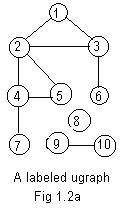
1,2,3, 2,3 are neighbors of node 1
2,1,3,4,5, 1,3,4,5 are neighbors of node 2
3,1,2,6,
4,2,5,7,
5,2,4,
6,3,
7,4,
8, 8 has no neighbors
9,10,
10,9,
A third method to represent the ugraph is a table in the form of a matrix. The end points of each edge are in the left column and in the upper row:
 ###              Incidence Matrix           *
         1     2     3     4     5     6     7     8     9    10
    1    0     1     1     0     0     0     0     0     0     0
    2    1     0     1     1     1     0     0     0     0     0
    3    1     1     0     0     0     1     0     0     0     0
  * 4    0     1     0     0     1     0    *1     0     0     0
    5    0     1     0     1     0     0     0     0     0     0
    6    0     0     3     0     0     0     0     0     0     0
    7    0     0     0     4     0     0     0     0     0     0
    8    0     0     0     0     0     0     0     0     0     0       Node 8 is isolated
    9    0     0     0     0     0     0     0     0     0     1
    10   0     0     0     0     0     0     0     0     1     0
For example, *4 heads a row and *7 heads a column that intersect at *1. So 4-7 is an edge. But 8 heads a row that interesects with any column at 0. No edge touches 8. Incidence matrices for ugraphs are always symmetric about the main diagonal, because each edge is repeated twice. Pseudo-edges are not included.
The incidence matrix ### is useful as input data to a computer. However it can be very large if there are many nodes. The adjacency list ## also can be used as input data to a computer. Also it requires much less space and is easier to make. Both adjacency lists and incidence matrices are used widely in graph theory.
F 1,2,3, 2,1,3,4,5, 3,1,2,6, 4,2,5,7, 5,2,4, 6,3, 7,4, 8,0, 9,10, 10,9//The clusters are separated by space(s) and // marks the end of the array. In each cluster the leading integer is first and represents a node, while the remaining integers in that cluster are secondaryintegers and are neighbors of that node.
The array F can be translated into a sequence of edges:
1-2 1-3 2-1 2-3 2-4 2-5 3-1 3-2 3-6 4-2 4-5 4-7 5-2 5-4 6-3 7-4 8-0 9-10 10-9Rearranging this sequence so that the same edge is repeated (except for the pseudo-edge 8-0):
1-2 2-1 1-3 3-1 2-3 3-2 2-4 4-2 2-5 5-2 3-6 6-3 4-5 5-4 4-7 7-4 8-0 9-10 10-9Now delete the second edge of each pair:
1-2 1-3 2-3 2-4 2-5 3-6 4-5 4-7 8-0 9-10This last sequence of edges (and pseudo-edge) can be written as an adjacency array:
S 1,2,3, 2,3,4,5, 3,6, 4,5,7, 8,0, 9,10//S has all the edges of Fig 1.2a, yet no edge is repeated. Excluding the pseudo-edge, S gives the exact number of edges, and is shorter than F. But in S not all the integer labels on nodes appear in bold. The node numbers 5,6,7,10 are not listed as leading integers of any clusters.
F gives twice the number of edges, excluding the pseudo-edge. All integer labels appear as leading integers of clusters. Moreover, the number of secondary integers in each cluster gives the degree of the node with the leading integer label.
For Fig 2.1a F is called the full adjacency array. S is called the short adjacency array. The adjectives full and short can be used only for adjacency arrays of ugraphs, not for adjacency arrays of digraphs.
The main difference of the two arrays is that in every cluster of any short adjacency array the leading integer is less than the secondary integers. But in F the secondary integers list all the neighbors of the leading integer. Intuitively speaking, S uses a minimum of integers, while F uses a maximum to represent the ugraph.
Of the two arrays for a ugraph, the full array (F) may be needed for processing correctly the data for a ugraph. But the short array (S) is easier to write down because it is shorter. It is not too difficult to convert one type of array into the other.
For a graph to be called labeled, integer labels have been assigned to all of its nodes. Sometimes it is desirable to replace these
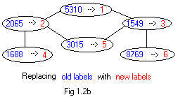 old labels with new labels without changing the basic sturcture of the graph. In figure 1.2b is a single ugraph with two labels assigned to each node. The old labels on the ugraph are valid but have an appearance of being random and large. The new labels on the same ugraph are smaller and more natural. The symbol --> means "is replaced by."
The same replacement can be by a horizontal listing: (the numbers being replaced are given in increasing order)
1549 --> 3
1688 --> 4
2065 --> 2
3015 --> 5
5310 --> 1
8769 --> 6
The same replacing of labels is defined by the following table. The numbers in the top row are replaced by the numbers in the bottom row. Also the numbers in the top row are placed in increasing order.
                   Table A  of replacing labels
                   1549 1688 2065 3015 5310 8769
                     3    4    2    5    1    6
A different table B, called the inverse table of A, can be obtained from table A by interchanging rows. Then the inverse table B can be used to restore old labels from the new labels.
                   Table B of replacing labels
                     1    2    3    4    5    6
                   5310 2065 1549 1688 3015 8769
Always the numbers in the top row are replaced by the numbers in the bottom row. The replacement table affects the replacement of integer labels in drawings and adjacency arrays.
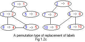 A much more common replacement is the replacement of integer labels 1,2,...N by integer labels of those same labels but in different order, called a permutation. For example in Fig 1.2c, the old integer labels are replaced by new integer labels according to replacement table C.
Table C of replacing labels using a permutation
  1  2  3  4  5  6  7  8  9 10
  1  6  2 10  3  8  7  4  5  9
The new labels in Fig 1.2d show that nodes with labels between 1 and 5 are in the piece (component) on the left, and nodes with labels between 6 and 10 are in the right piece (compoonent) of the graph.
The number of ways that the red numbers can be chosen to replace the blue numbers is 3 628 800. In general, if there are N nodes in a graph, then there are
1 --> 1 2 --> 2 3 --> 3 ..................... N --> N
This "brute force" method is not practical on the common desk top computer if the number of nodes is relatively large, say greater than 12. It may not possible for any computer if the number is moderately large, say 20. The number of assignments (permutations=2432902008176640000) is too large, even with "smart" computer programs that eliminate many assignments that give equal adjacency arrays. This suggests that the determination of equivalence of some ugraphs with many nodes and many edges may be difficult if not impossible. Much time may be wasted trying to show that two large or even relatively large ugraphs are equivalent or not equivalent by this method of reassigning integer labels and comparing adjacency arrays.
True or false: all ugraphs with exactly 3 nodes and exactly 2 edges are equivalent?
True or false: any ugraph with exactly 4 nodes and exactly 3 edges is equivalent to one of the ugraphs shown in Fig 1.3d, Fig 1.3e, Fig 1.3f .
True or false: If two labeled ugraphs are equivalent then they have the same adjacency arrays.
True or false: all complete ugraphs with exactly 5 nodes are equivalent May the number 5 be replaced by any positive integer to get a true statement?
Draw two non-equivalent ugraphs with exactly 4 nodes and 2 edges each.
Return to main text: top / section 1.3
filler
filler
filler
filler
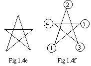 In Fig 1.4e a star has five line segments. It is a trivial task to draw the star using a pen or pencil. Draw line segments in any order. It is not difficult to find a way of drawing all five line segments without lifting the pen from the paper. But can it be done without drawing any line segment twice?
The answer is yes. In Fig 1.4f is an equivalent ugraph. It has been labeled in a special way. The directed path 1->2->3->4->5->1 shows how motion traverses every edge once and only once. Motion enters at node 1.
A (directed) path is Eulerian if it traverses every edge in a ugraph once and only once. (Leonard Euler was a mathematician from Germany.) If motion returns to its start node then the directed path is called a Eulerian loop or Eulerian circuit.
 There is no Eulerian path in the ugraph shown in Fig 1.4g.
From any node to any other node there is a directed path. It is not difficult to find a path that "covers" the entire ugraph. Most likely, it will traverse the same edges and the same nodes more than once. Three questions arise involving a single path::
(1) Is it possible to visit every node, but only once each time?
(2) Is it possible to traverse every edge, but only once each time?
(3) Is it possible to traverse every edge only once each time, and return to the starting node?
If such a path (1) exists it is called Eulerian, named after the German mathematician Euler. If a path (2) exists it is called Hamiltonian, named after the Irish mathematican Hamilton. If a path (3) exists, it is called a Hamiltonian circult.
Some real life scenarios may motivate the discussion of these paths.
Return to main text: top / section 1.4