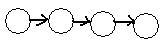
 During the journey the bug most often enters a node from some link and goes out of that node along a different link. The task is simple for traversing all the nodes in the linear graph in the adjacent figure from left to right.
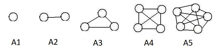
The adjacent figure shows graphs A1, A2, A3, A4 and A5 that have 1,2,3,4 and 5 nodes respectively. Focus attention on A4. Each node in graph A4 has degree 3 (three links contact any node).Adding all these contacting links gives 3+3+3+3 = 12. But A4 shows only 6 links, because 3+3+3+3 counts each link twice (each link has two ends.)
The number of links in a complete graph with N nodes = N(N-1)/2.
The above array can be translated into a sequence of edges:
1-2 2-1 1-3 3-1 2-3 3-2 2-4 4-2 2-5 5-2 3-6 6-3 4-5 5-4 4-7 7-4 8-0 9-10 10-9Now delete the second linked nodes of each pair:
1-2 1-3 2-3 2-4 2-5 3-6 4-5 4-7 8-0 9-10This last sequence of edges (without the pseudo-link) can be written as a short graphical array:
S (1),2,3, (2),3,4,5, (3),6, (4),5,7, (9),10S has all the links of Fig 1.2a, yet no link is repeated. Excluding the pseudo-link, S gives the exact number of links. But in S not all the integer labels on nodes appear in parentheses. The node numbers 5,6,7,10 are not listed as leading integers of any clusters because their neighbors have lower numbers.
Even for some pair of Ugraphs with only 25 nodes each, the checking of all the permutations for graphical equivalences is incredibly numerous. To see this, notice that the number of permutations is 25! = (approximately) 1.55x1025. Suppose the computer can check 1 billion (109) permutations each second. There are 3.15x10⁷ seconds in each year. This means that the computer can check
The computer controls a robotic bug . It directs the bug to visit all the nodes in a connected Ugraph. There must be a first node which marks the start of the journey of the bug about the graph, and a last node when the bug has finished the task.
During the journey the bug most often enters a node from some link and goes out of that node along a different link. The task is simple for traversing all the nodes in the linear graph in the adjacent figure from left to right.
The journey is more complicated if some nodes have more than one way out (degree 3 or higher). In each of those nodes a decision must be made: which exit to select. In the chapter 4 the computer will use numbers assigned to all the links to be used for the choice of exits from nodes. In this discussion the numerical labels assigned to each node will be used. In the full adjacency array a list of all of its adjacenct neighbors after each (node). The following method can be used: when the bug is in a node with more than one exit, the computer which sees only (the equivalent to) the long adjacency array selects the neighbor with the lowest label number and the bug exits along the link that leads to that neighbor.
Three common problems arise and additional parts will be added to this method to produce a universal solution:
(a) while trying to visit all nodes the bug may visit some nodes more than once;
(b) by choosing every time a neighbor with the smallest label number the bug may traverse an endless loop;
(c) after moving along a path through nodes, the bug may enter a node with no other way out.
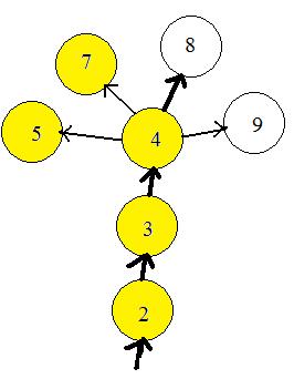 The computer can prevent the bug from entering any node more than once, by remembering what nodes have been visited. It puts a mark by the label number if the node has been visited. In the adjacent figure the nodes already visited are colored yellow. The computer bug has already visited nodes 5 and 7 during travels in another part of the graph (not shown).The bug has moved along through nodes 2 and 3 and has entered node 4, coloring the nodes as it enters. The unvisited neighbor of node 4 with the lowest number label is nod 8. The bug exits node 4 and goes to 8. Then node 8 will become yellow. The computer will actually put a mark by label 8. The avoiding of nodes already visited solves problems (a) and (b).
There are two types of nodes with no exits: (1)a leaf (node of degree 1) has an entrance but no exit, and (2) all the neighbors of a node have already been visited. Both problems are solved by allowing the bug to back up until it finds a node with one or more unvisted neighbors. Therefore, a bug must allowed to back up into a visited node, but not go forward into a visited node. With this agreement, no node will be visited more than once.
This backing up procedure has a problem. When the bug is in the last node, then all nodes have been visited. Backing up will take the bug all the way back to the first node where it entered the graph. The computer cleverly created an "artificial node" not part of the graph, and assigned it the prohibited number label 0 (zero). The artificial node is linked artificially with the first node where the bug entered the graph. Since all nodes of the graph have been visited, the bug in the first node will back up into the artificial node. The computer detects the label 0 and terminates the program.
The computer may list all the visited nodes. The list should be a permutation of all the label numbers, that is, a permutation of 1,2,...,n, where n = number of nodes.
Two comments should be made. The choice of the neighbor of a (node) with the smallest label number may be changed to the choice of the neighbor that has not yet been visited and has the largest label number. The printout of all the visited nodes will be another permutation of 1,2,...,n. Other systematic selections of neighbors will produce new permutations.
The above procedure of a travelling bug can be extended to Ugraphs that are not connected. After the bug has visited all nodes in a component it backs up into the zero node, the computer checks to see if any node in the graph has not yet been visited. If any exist it selects the unvisited node with the smallest label number, attaches the zero node to it and the bug enters that node. By this method all the nodes of the graph will be visited. More useful is the printing out all the nodes in each component separately. In this way the computer reveals all the components of the graph.
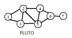 The adjacent drawing shows a graph PLUTO. The following steps create and place the defining information about the graph into the computer.
Step 1. Create an adjacency list for the graph.
The long adjacency list for it is
(1),2,3
(2),1,3,4,5
(3),1,2,5
(4),2,5,6
(5),2,3,4,6
(6),4,5,7
(7),6
Removing the red numbers produces the short adjacency list. The black numbers are needed for the input. The red numbers may or may not be included.
Step 2. Click on the link Computer (InputDataU) to go to a list of executable computer programs. There, click on the program InputDataU to start the program. (The U means that the input-data is from a Ugraph.)
Step 3. Answer the questions from the computer.
Where is the input-data for the Ugraph?
If it will be typed in on the (K)eyboard, type K (it will be typed in )
If it is already in the GraphData (F)ile, type F
K <--- ans.
Not exceeding 10 characters, input name of graph PLUTO <--- ans.
Input number of nodes: 7 <--- ans.
Input every neighbor with higher natural number after each (node):
(1),2,3 <--- ans.
(2),3,4,5 <--- ans.
(3),5 <--- ans.
(4),5,6 <--- ans.
(5),6 <--- ans.
(6),7 <--- ans.
(7), <--- no ans.
During the conversation about (node) and their neighbors, the computer prints out the(node), and the numbers (neighbors) and commas after it are typed in as answers.
The computer prints out the following information about the graph:
Ufile PLUTO 7 Nodes 10 Links
The array of degrees:
(1)2 (2)4 (3)3 (4)3 (5)4 (6)3 (7)1
The long adjacency array is:
(1),2,3, (2),1,3,4,5, (3),1,2,5, (4),2,5,6, (5),2,3,4,6, (6),4,5,7, (7),6,
The short adjacency array is:
(1),2,3, (2),3,4,5, (3),5, (4),5,6, (5),6, (6),7, (7),
Change data?
if YES then press Y key. Pressing any other letter key means NO n
[U "PLUTO", (1),2,3, (2),3,4,5, (3),5, (4),5,6, (5),6, (6),7, (7)]
The computer stores the input-data including the brackets [ ] in a text file. If the graph is used again, the input data can be retrieved from the file (ans. F instead of K).