Return to Chapter 5
Additional Material for Chapter 5:
Linear Transformations
Images of points which are not collinear
A non-singular linear transformation carries non-collinear points onto non-collinear points.
Notation: if A,B,C are not collinear and L is non-singular, then L(A),L(B),L(C) are not collinear.
(Indirect argument) Suppose that L is non-singular. Then L has an inverse L-1. Suppose L(A),L(B),L(C) are collinear. then apply L-1 to these three points to get L-1L(A), L-1L(B), L-1L(C). Since L-1 is a lintr, by [2.3] these three points are collinear. But these three points are A,B,C which by hypothesis are not collinear. This is a contradiction. Hence L(A), L(B),L(C) must be non-collinear. Therefore the theorem is true.
Linear transformations carry segments onto segments
The line segment joining two points A and B is obtained by "filling in" the portion of the plane between A and B with points P, where
(α + β)p = αa + βb
and where coefficients α and β are numbers between 0 and 1. Apply L to both sides of this equation to get
(α + β)L(p) = αL(a) + βL(b)
This equation fills in the portion of the plane between L(A) and L(B) with points L(P). But this is the segment joining L(A) and L(B). Therefore, a lintr carries segments onto segments. For this to be unconditionally true, a segment may exist even if its end points coincide. (Such a segment has zero length.)
If L(A) and L(B) are distinct points, then by letting α and β be any real numbers, the above equations show that L carries a line onto a line. These facts show that a lintr is a "nice" geometric function.
Steps for discussions of actions on the plane
For some physical actions on materials and corresponding geometric actions on the plane linear transformations are developed. To discuss these developments a plan of six steps is followed:
(A) The action is described physically, simply and intuitively. The image point of any given point is located by physical means.
(B) The action is described by synthetic geometry on a plane without coordinates. A simple geometric construction locates the image point from the given point (if the point is not carried back onto itself. such as the origin).
(C) On the plane with coordinates the action carries the special points (1,0) and (0,1) onto images, the coordinates of which are calculated using geometry.
(D) From the transposes of the images of the special points, a matrix is formed which will become the associated matrix of the linear transformation L in the next step.
(E) From those images a linear transformation L is created: L(x,y) = x(image of (1,0)) + y(image of (0,1));
(F) It is essential to show that what the linear transformation L does to any point, is the same as what the geometric description or construction in step (B) does for that same point, namely, the images located by L and by synthetic geometry are the same.
Some review of trigonometry
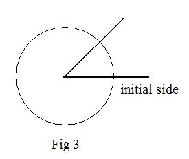
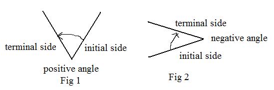 A half line has a single endpoint. Two half lines with a common endpoint form an angle. That common point is called the vertex of the angle. Allow the half lines to coincide to produce a zero angle. The angle is measured going from one half line, called the initial side, to the other, called the terminal side. In going from the initiial side to the terminal side there are two circular directions for measuring the angle. The measure is positive using the counterclockwise direction (Fig 1), and negative using the clockwise direction (Fig 2).
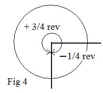
For measuring an angle it is sometimes convenient to place the vertex of the angle at the center of a circle. (In textbooks on geometry that is called a central angle.) An angle is in standard position if its initial side is horizontal to the right of the vertex (Fig 3).
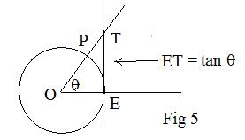
 There are three common measurement systems for angles: revolutions, degrees and radians. An angle of 1 rev is actually a complete curcular turn, so that the terminal side coincides with the initial side. A +1 rev and a -1 rev indicate in which circular direction the revolution is taken. For an angle of 1/2 rev (or -1/2 rev) the initial and terminal sides form a straight line. It is also called a straight angle. An angle of 1/4 rev is a right angle with the terminal side perpendicular to the initial side.
Notice that the sides of an angle that measures -1/4 rev coincides wiith the sides of an angle that measures +3/4 rev (Fig 4). For an angle of 0 rev, the two sides coincide.
There are three common measurement systems for angles: revolutions, degrees and radians. An angle of 1 rev is actually a complete curcular turn, so that the terminal side coincides with the initial side. A +1 rev and a -1 rev indicate in which circular direction the revolution is taken. For an angle of 1/2 rev (or -1/2 rev) the initial and terminal sides form a straight line. It is also called a straight angle. An angle of 1/4 rev is a right angle with the terminal side perpendicular to the initial side.
Notice that the sides of an angle that measures -1/4 rev coincides wiith the sides of an angle that measures +3/4 rev (Fig 4). For an angle of 0 rev, the two sides coincide.
The absolute value of an acute angle measures between 0 and 1/4 rev. The absolute value of an obtuse angle , between 1/4 and 1/2 rev. The absolute value of a reflex angle, between 1/2 and 1 rev. The positive angle in Fig 4 is a reflex angle.
A circle can be divided into 360 congruent arcs. An angle whose sides pass through the end points of any of these arcs has the measure of 1 degree (1°). Then 360° = 1 rev. 180° = 1/2 rev. = 1 straight angle, 90° = 1/4 rev = 1 right angle. Each degree can be divided into 60 minutes, and each minute can be divided into 60 seconds. But these fractional parts of a degree will seldom be used in discussions in these volumes.
A geometric definition of the basic functions sine, cosine and tangent uses the unit circle, a circle with radius of unit length. In the adjacent figure a unit circle in the xy-coordinate plane with center at the origin. An angle in standard position has its vertex at the center at the origin O and its initial side along the positive x-axis. Let E denote the fixed intersection of the positive x-axis with the unit circle. Let P be any point on the unit circle. Then half line OP is the terminal side of an angle EOP.
Altlhough not used in these discussions the radian measure of angle EOP is the length of arc on the unit circle from E to P. It is positive or negative according to the direction, counterclockwise or clockwise. Since the circumference of a circle with radius 1 is 2π, 2π radians = 1 rev = 360°, π radians = 1/2 rev = 180°, π/2 radians = 1/4 rev = 90°
The Greek letters θ, φ, and ω are often used to denote angles or their measurements.
For any point P that is on the unit circle, let θ be the measure of the angle EOP. But P must have coordinates. By definition, they are P(cos θ, sin θ). Using this definition, values for the cosine and sine are immediately determined from the coordinates of P when P is 0 rev, 1/4 rev, 1/2 rev, 3/4 rev:
cos 0° = 1, sin 0° = 0, P = E and has coordinates (1,0)
cos 90° = 0, sin 90° = 1, P is at the top of the unit circle and has coordinates (0,1)
cos 180° = -1, sin 180° = 0, P is at the extreme left of the unit circle and has coordinates (-1,0)
cos 270° = 0, sin 270° = -1, P is at the bottom of the unit circle.
The negative angles -180° and - 90° locate P at the extreme left on the circle and at the bottom of the circle. Therefore,
cos -180° = -1, sin -180° = 0
cos -90° = 0, sin -90° = -1
For any angle θ, point P(cos θ, sin θ) is at a unit distance from the origin. Therefore by the distance formula
cos2 θ + sin2 θ = 1
The following are identities involving the sum of two angles θ + φ and their difference θ - φ:
cos(θ + φ) = cos θ cos φ - sin θ sin φ
cos(θ - φ) = cos θ cos φ + sin θ sin φ
sin (θ + φ) = sin θ cos φ + cos θ sin φ
sin (θ - φ) = sin θ cos φ - cos θ sin φ
Setting φ = 90° produces the identities
cos(θ + 90°) = - cos θ, cos(theta; - 90°) = sin θ
sin(θ + 90°) = cos θ, sin (θ - 90°) = - cos θ
Setting θ to 0° and to 90° in two of the above identities, and replacing φ by θ produces identities
cos (-θ) = cos θ, sin (-θ) = - sin θ
The tangent may be defined as a quotient tan θ = sin θ/cos θ .This makes tan 90° undefined because the denominator cos 90° = 0. Similarly, tan 270° is undefined. If a vertical line is made tangent to the circle at E then tan θ = the directed length of E to the intersection T of the terminal side of the angle through P and the vertical line.
Orientation
There are various methods of associating points in the plane. Using the prime notation, points A, B, C and A', B', C ' are often associated respectively. In more rare cases, A, B, C and A*, B*, C* are associated respectively. Most often some function relates points and their images. For example, A, B. C and L(A), L(B), L(C) are related respectively, where L is a linear transformation on a plane. It is the labelling of figures that give them "orientations."
The association can be extended to lines and line segments. All the points on one line or line segment are associated with all the points on another line or line segment.For line segments it is enough for the end points to be associated. For example,
_______________ ________
are two parallel line segments. Suppose the end points are labeled as follows:
A_______________B A'________B'
or they could be labelled as:
A_______________B B'________A'
In the first labelling, AB and A'B' are said to have the same orientation. In the second labelling AB and B'A' are said to have opposite orientation.
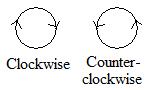 Circular motion can also be given orientation. There are two ways to go around a point: clockwise and counter-clockwise. The hands of a clock always go clockwise.However, looking down at a race track, the cars racing on it may go in a counter-clockwise motion. Motion going clockwise areound a point and motion going counter-clockwise around a point are said to have opposite (circular) orientation. If the motions are both clockwise or both counter-clockwise, they are said to have the same (circular) orientation.
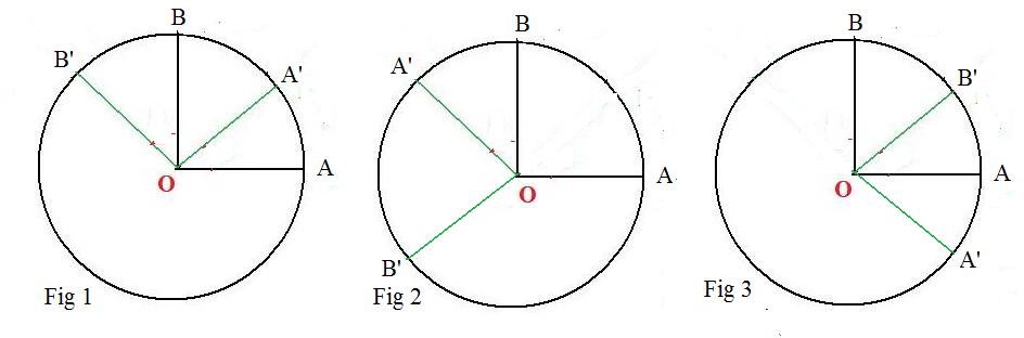
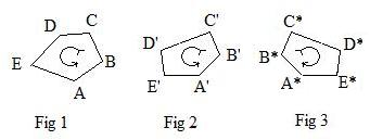 The same is true with the labelling of two simply closed polygons. The adjacent vertices of one polygon are labelled with letters in alphabetic order or numbers in increasing order. There is an association between the vertices of the first polygon and the vertices of the second polygon. If the two orderings are both clockwise or both counter-clockwise (see Fig 1 and Fig 2) then the two polygons have the same orientation. But if they have opposite orderings (see Fig 1 and Fig 3), then they have opposite orientations.
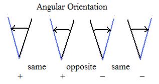 Angles may have an initial side and a terminal is a motion about the vertex. It may be clockwise or counter-clockwise. If the motions are both clockwise or both counter-clockwise for two angles in a plane, then the angles have the same (angular) orientation. If one is clockwise and the other is counter-clockwise then they have oppossite (angular) orientation.
In circular mostion, it is customary to call counter-clockwise motion positive, and clockwise motion negative. But usually it is more important to compare orientations, that is, see if two orientations involved are the same or opposite.
Intuitive statement of the following discussion
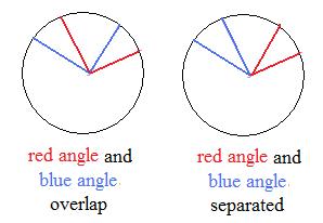 Without color the two figures to the right show two congruent figures, two circles with four radii in each. With color there is a pair of angles in each circle. If the red and blue angles are congruent in one figure then the red and blue angles are congruent in the other figure. Notice that the red angle in one figure is not contruent to the red angle in the other figure, nor are the blue angles congruent. Congruency of angles need ot occur between figures, but may occur inside each figure.
Orientation and arcs of circles
Given a circle as shown. Let O be the center of the circle. The figure shows a darkened connected arc of the circle. An arc has a length. Now put a -> shaped head on the arc at either end. (The end point not receiving the > is called the tail.) Then it has become a sort of "bent vector." By putting a head on it, the arc receives an orientation. This bent vector is better called an arc with orientation or a . Notice that there are two and only two possible orientations that the directed arc can have. One choice will make the directed arc bend to the left, and the other choice will make the direct arc bend to the right. this gives one method to designate orientations given to arcs: it causes the arc to appear bent to the left or it causes the arc to appear bent to the right. (A way to remember this, the center of the circle acts as a magnet, attracting the head and tail of the directed arc, but not the middle, toward the center. Either orientation causes this attraction.)
Consider now a circle in the coordinate plane with center at the origin.There is a semi-circle above the horizontal x-axis and a semi-circle below the horizontal x-axis. The y-coordinate of every point on the upper semi-circle is positive, while the y-coordinate of every point on the lower semi-circle is negative. Therefore, call the upper semi=circle positive and the lower semi-circle negative. Both semi-circles have a common point A at their intersections with the positive x-axis. For any point P on the upper semi-circle the directed arc AP.bends to the left. Therefore bending to the left is positive bending.. For any point Q on the lower semi-circle, the directed arc AQ bends to the right. Its bending to the right is negative bending.
It is possible to make a definition here:
(*) (Positive and negative orientation according to bending) A directed arc of any circle has positive orientation if and only if it bends to the left . It has negative orientation if and only if it bends to the right.
Relating negative orientation to movement of the hand of a clock provides an easier way to distinguish positive and negative orientations of directed arcs. As time increases the tip of the large (minute) hand traverses a circle with time intervals that create directed arcs which always bend to the right. For example, if 15 minutes elapse, the tip traverses 1/4 of the circle. It traces a directed arc that bends to the right. Therefore, all directed arcs made by the moving tip of the laarge hand of a clock have negative orientaation. Trying to create positive directed arcs along that same circle is contrary to advancing time.
(**) (Positive and negative orientation according to a clock) A directed arc of any circle has negative orientation if and only if movement from tail to head is clockwise, the same way as movement of the tip of the hand of a clock. It has positive orientation if the movement is the counterclockwise, opposite to the movement of the tip of the hand.
It is sometimes important to compare the orientations of two directed arcs, that is, if they have the same or opposite orientations:
(a) Just looking at the directed arcs and using (**) above may decide.
(b) Another way is to fix one directed arc, and slide the other around in a forward motion. If the heads will collide then they have opposite orientation. If the heads do not collide after contact then they have the same orientation.
(c) A third way uses the following lemma. However, the arcs must be congruent.
Lemma Geometric comparison of orientations)
(a) Two directed arcs on the sme circle are congruent and have the sme orientation if the line segment joining the head point of the first arc to the tail point of the second arc has the sme length as the line segment joining the tail point of the first arc to the head point of the second arc.
(b) Two directed arcs on the sme circle are congruent and have opposite orientations if the line segment joining the head points both arcs has the same length as the line segment joining the tail points of botharcs.
[3.0a] (Determinants and orientations of arcs) In the coordinate plane, let P(α,β) and Q(γ,δ) be any pair of points on a circle with center at origin O. Then directed arc PQ has positive (counter-clockwise) orientation if and only if the determinant
 is positive. Similarly, arc PQ has negative (clockwise) orientation if and only if the determinant is negative.
Orientation of arcs of a circle
A segment is a connected part of a straight line. Fig 1 shows it as the darkened part of a straight line. An arc is a connected part of a circle. It also has finite length. Fig 2 shows it as the darkened part of a circle. Both the segment and the arc can be given an orientation by indicating which way they point. The segment then becomes a vector while the arc becomes a directed arc. The point at which the vector or arc points is called the terminal point of the vector or directed arc. The other end locates the initial point. So a directed arc points from its initial point to its terminal point. Intuitively speaking, a directed arc is like a bent vector.
The tip of the large hand of a clock moves along a circular path. Such a motion is called clockwise. Notice that the center of the clock is to the right of the path of the motion. Motion going opposite is called counter-clockwise. The center of the clock is to the left of such motion. This idea of giving orientation to directed arcs is obvious. A directed arc has the clockwise orientation if the center of the circle is to the right of the arc. The directed arc has the counter-cliockwise orientation if the center is to the left of the arc. Looking at any race track in the USA from above, most racing cars go along the track with a counter-clockwise orientation.
A directed arc is given an orientation by noticing which side the center of the circle is located. If the center is left of the arc, then the orientation of the arc is counter-clockwise. If the center is right of the arc then the orientation is clockwise.
Although counter-clockwise motion is often designated as positive orientation, and clockwise motion is negative orientation, it is often more important to compare orientations, without specifying what they are. Two arcs may have the same orientation if they both have clockwise or both have counter-clockwise orientation. They have opposite orientations if one arc has clockwise orientation and the other has counter-clockwise orientation.
For any two points P and Q on a circle therre are two directed arcs joining P to Q. The arcs have opposite orientations. Unless specified otherwise, the phrase arc PQ will mean the shorter (minor) arc. Therefore, without conditions no arc is longer than a semicircle.
Construct a circle with center at the origin of the coordinate plane. A directed arc whose initial point is the intersection of the circle and the positive x-axis is said to be in standard position. Because arcs are never longer than semicircles, the terminal point of a directed arc in standard position can never be to the left of the y-axis, that is, the x-coordinate of the terminal point of an arc can not be negative. But the y-coordinate may be positive, zero or negative.
If the terminal point of a directed arc in standard position is above the x-axis, then the y-coordinate is positive and the arc has positive (counter-clockwise) orientation.
If the terminal point of the directed arc in standard position is below the x-axis, then the y-coordinate is negative and the arc has negative (clockwise) orientation.
In other words,
The sign of the y-coordinate of the terminal point of a directed arc in standard position determines the sign of the orientation of the arc.
Determinants and orientation of arcs of a circle
[3.0c] (Positive or negative orientation according to a determinant) In the coordinate plane, let P(α,β) and Q(γ,δ) be any pair of points on a circle with center at origin O.
(i)Then directed arc PQ has positive orientation if and only if the determinant
is positive.
(ii) Similarly, directed arc PQ has negative orientation if and only if the determinant is negative.
Lemma1: A rotation about the center of a circle carries perpendicular radii onto perpendicular radii.
Also, the angles between the two pairs of radii are congruent and have the same orientation.
 Given: points A, A', B, B' on a circle with center at O, such that a rotation about O carries A and B onto A' and B' respectively.
Also given: segments OA and OB are perpendicular.
To prove that segments (images) OA' and OB' are perpendicular.
Note: all arcs and angles are directed, that is, they are measured counter-clockwise. ALso equalities between angles and equalities between arcs mean congruence.
By definition of rotation, angle AOA' = angle BOB'. Therefore,
(*) arc AA' = arc BB'
There are two possibilities.
Case 1: 0° <= angle OA' < 90° (Fig 1)
Then B is on arc A'B'. Add arc A'B to both sides of equation (*). to get
(**) arc AB = arc A'B'
Therefore,
(***) angle AOB = angle A'OB'
Since angle AOB = 90° then so must angle A'OB' = 90°. Hence segments OA and OB are perpendicular.
Case 2: 90° <= angle AOA' < 360° (Fig 2 and Fig 3)
Then A' is on arc BB'. Subtract arc BB' from both sides of equation (*) to get equation (**) and equation (***) follows.
Since angle AOB = 90° then so must angle A'OB' = 90°. Hence segments OA and OB are perpendicular.
Actually a stronger statement, lemma2 below, is proven after some modification of the above argument. In particular, replace 90° by an arbitrary angle θ.
Lemma2: A rotation about the center carries the central angle between two radii onto two radii with a congruent central angle that has the same orientation.
For support see statements at the end of the discussion for Lemma1 above.
Lemma3: An orthogonal reflection about a diameter of a circle carries perpendicular radii onto perpendicular radii and corresponding central right angles have opposite orientation.
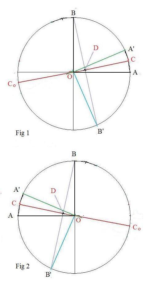
Given: a circle with center at O, diameter CCo,
&nbnsp; perpendicular radii OA and OB,
images A', B' etermined by a reflection of points A, B about CCo
To prove: radii OA' and OB' are perpendicular.
Note: all arcs mentioned in this discussion are minor. Equality between arcs means congruence. In Fig 1 all arcs and angles are measured counterclockwise and are positive. In Fig 2 they are measured clockwise and are negative. Both figures belong to the following discussion. They show two different ways CCo may be slanted
From the definition of reflection about a line, CCo is the perpendicular bisector of segment AA' and segment BB'. Therefore,
arc B'C = arc CB and arc CA' = arc AC
Adding these two equations together produces the equality
arc B'A' = arc AB
This equality of arcs makes the corresponding central angles congruent. But angle AOB is a right angle. Therefore, angle B'OA' is a right angle with the same orientation as angle AOB. This can be stated angle A'OB' is a right angle, but with opposite orientation as angle AOB. Since angle A'OB' is a right angle, OA' is perpendicular to OB'.
Actually a stronger statement, lemma4 below, is proven after some modification of the above argument. In particular, replace the right angle by an arbitrary angle θ.
Lemma4: An orthogonal reflection about a diameter of a circle carries the central angle between two radii onto two radii with a congruent central angle that has the opposite orientation.
For support see statements at the end of the discussion for Lemma3 above.
Reflection of the special points about a line through the origin
A reflection about the line with inclination angle θ carries (1,0) and (0,1) onto the points
(cos 2θ, sin 2θ) and
(sin 2θ, cos 2θ)
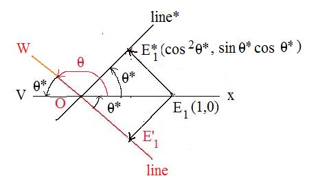
 Case 1: The lineo of L goes from lower left to upper right (Fig 2a). Then
0° < θ < 90°
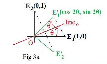
Then the special point E1 is reflected across lineo to produce point E'1. (Fig 3a). There remains the finding of the coordinates of this point. using
(1) angle E1OE'1 = 2θ
By definition of sine and cosine on the unit circle,
(2) E'1(cos 2θ, sin 2θ)
The next task is to find the coordinates of E'2. Since L preserves distance, it also preserves angles. Therefore, angle E'2OE'1 is congruent to angle E2OE1 which is -- 90° measured in the clockwise direction. Hence,
(3) angle E1OE'2 = 2θ -- 90°
Now the following are identities from trigonometry. (Click here to see the evaluations.)
(4) cos (2θ -- 90°) = sin 2θ,
sin (2θ -- 90°) = -- cos 2θ
Again by definition of sine and cosine on the unit circle,
(5) E'2(cos (2θ -- 90°), sin (2θ -- 90°)) = E'2(sin 2θ, - cos 2θ)
Therefore,
(6) E'2(sin 2θ, - cos 2θ)
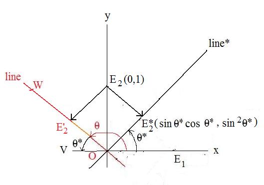
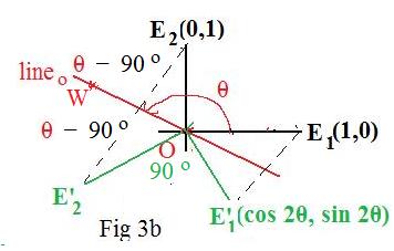 Case 2: The lineo of L goes from lower right to upper left (Fig 2b).
90° < θ < 180°
Let W be any point on lineo in the quadrant II.
Here E2 is reflected about lineo onto point E'2 making two congruent angles
E2OW = WOE'2
Because the x-axis and y-axis are perpendicular,
angle E2OW = θ -- 90°
Therefore
WOE'2 = θ -- 90°
To get the reflex angle from the positive x-axis (E1 is on it) to OE'2 add θ to the above angle
WOE'2
(3') angle E1OE'2 = 2θ -- 90°
But (3') and (3) are identical. Equations (4) and (5) lead to
(6') E'2(sin 2θ, - cos 2θ)
which is identical to (6).
Case 2: The lineo of L goes from lower right to upper left (Fig 2b).
90° < θ < 180°
Let W be any point on lineo in the quadrant II.
Here E2 is reflected about lineo onto point E'2 making two congruent angles
E2OW = WOE'2
Because the x-axis and y-axis are perpendicular,
angle E2OW = θ -- 90°
Therefore
WOE'2 = θ -- 90°
To get the reflex angle from the positive x-axis (E1 is on it) to OE'2 add θ to the above angle
WOE'2
(3') angle E1OE'2 = 2θ -- 90°
But (3') and (3) are identical. Equations (4) and (5) lead to
(6') E'2(sin 2θ, - cos 2θ)
which is identical to (6).
The linear transformation defined by (*) below is the orthogonal reflection about the line
The line is shown in the adjacent figure. It passes through the font color="red">origin and has the inclination angle θ.
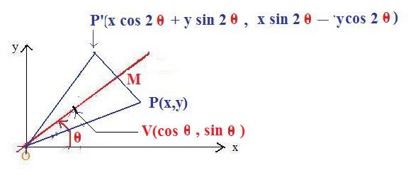
Let L be a linear transformation defined by
(*) L(x,y) =
(x cos 2θ + y sin 2θ,
x sin 2θ -- y cos 2θ)
For any point P, P' = L(P). The plan is to show that P'OP is an isosceles triangle and the
line bisects this triangle.
If P(x,y) then P'(x cos 2θ + y sin 2θ, x sin 2θ -- y cos 2θ)
|OP'|2 =
(x cos 2θ + y sin 2θ)2 + (x sin 2θ -- y cos 2θ)2 =
x2 cos2 2θ + 2xy cos 2θ sin 2θ + y2 sin2 2θ +
x2 sin2 2θ -- 2xy cos 2θ sin 2θ + y2 cos2 2θ =
x2(cos2 2θ + sin2 2θ) +
y2(sin2 2θ + cos2 2θ) = >br>
x2 +y2 = |OP|2
Therefore OP' and OP are congruent. The triangle P'OP is isosceles.
The unit circle with center at O (not drawn) intersects the line at some point V. Then OV is a segment that is part of the line By definition of sine and cosine, V(cos θ, sin θ).
The inner product PP'*OV =
(x cos 2θ + y sin 2θ -- x,
x sin 2θ -- y cos 2θ -- y) * (cos θ, sin θ) =
(x cos 2θ cos θ + y sin 2θ cos θ -- x cos θ)
+
(x sin 2θ sin θ -- y cos 2θ sin θ -- y sin θ) =
x(cos 2θ cos θ + sin 2θ sin θ -- cos θ)
+
y(sin 2θ cos θ + cos 2θ sin θ -- sin θ) =
x(cos(2θ -- θ) -- cos θ)
+
y(sin(2θ -- θ) -- sin θ) =
x(cos θ -- cos θ)
+
y(sin θ -- sin θ) =
0.
Therefore PP' is perpendicular to OV which means that PP' is perpendicular to line
Let M be the intersection of PP' and the line.
Right triangle POM is congruent to right triangle MOP' (hyp-leg = hyp-leg) This guarantees that the line is the perpendicular bisector of segment PP'.
This, in turn, means that L reflects point P across the line onto P'.
Rotation of the special points about the origin through a given angle
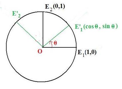 A rotation through angle θ carries points (1,0) and (0,1) onto the points (cos θ, sin θ) and (=sin θ, cos θ) respectively.
Let E1 and E2 be the names of the special points (1,0) and (0,1): E1(1,0) and E2(0,1). Let E'1 and E'2 be their images after rotation. Let θ be the angle of rotation. Then
angle E1OE'1 = θ and angle E2OE'2 = θ
Since the circle is the unit circle
E'1(cos θ, sin θ)
But
angle E1OE'2 = angle E1OE2 + angle E2OE'2 = 90° + θ
Then by definition
E'2(cos (θ + 90°), sin (θ + 90°)) = E'2(-sin θ , cos θ)
Therefore the rotation carries the special points (1,0) and (0,1) onto (cos θ, sin θ) and (-sin θ , cos θ) respectively.
General formula for rotation
The linear ttransformation L defined by
L(x,y) = (x cos θ -- y sin θ, -x sin θ + y cos θ)
is the rotation about the origin through angle θ.
Let θ be the angle of the rotation. Let P(x,y) be any point (except the origin), and P'(x',y') the image L(P). To show that the rotation carries P onto P', that is, that the rotation and L do the same thing. There are two things to show:
(a) points P and P' are on the same circle with center at O;
(b) the angle POP' = the angle of rotation (θ).
To show (a) it is sufficient to show that |OP'|2 = |OP|2. This is done through a chain of equalities.
|OP'|2 =
|(x cos θ + y sin θ, -x sin θ + y cos θ)|2
=
(x cos θ + y sin θ)2 + (-x sin θ + y cos θ)2
=
x2 cos2 θ + 2xy cos θ sin θ + y2 sin2 θ
+
x2 sin2 θ -- 2xy sin θ cos θ + y2 cos2 θ
=
x2(cos2 θ + sin2 θ)
+
y2(sin2 θ + cos2 θ)
=
x2 + y2
=
|(x,y)|2
=
|OP|2.
-----
To show (b) it is sufficient to show that the inner product (of vectors)
OP * OP' = |OP| |OP'| cos θ, that is, this inner product uses the angle of rotation.

OP * OP' =
(x cos θ + y sin θ, -x sin θ + y cos θ) * (x,y)
=
x2 cos θ + xy sin θ -- xy sin θ + y2 cos θ
=
x2 cos θ + y2 cos θ
=
|OP|2 cos θ
=
|OP| |OP'| cos θ
Projection of the special points onto a line through the origin
Case 1: The line goes from lower left to upper right (0° < θ < 90°)
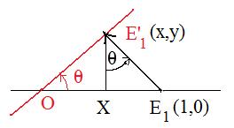 Case 1a: projection of special point E1(1,0) onto the line making image point E'1
Let E1(1,0) denote the special point, and let E'1 be the projected image. Since the coordinates of this projected image are to be found, let them be (x.y) where x and y are unknowns whose values are to be found.
Drop a perpendicular from E'1 to the x-axis making the point X there. Notice that
|OE1| =1 and |OX| = x As a result there are two right triangles
right triangle E1E'1O and right triangle E1XE'1
Let θ (black) = angle XE'1E1.
Angle OE1E'1 is in both of the triangles and therefore is equal to both
90° -- θ and 90° -- θ
Therefore θ = θ.
SThe coordinates of this projected image E'1 are to be found. Let x and y be the unknown coordinates. So E'1(x,y) is the complete representation of the image.
In right triangle E1XE'1,
tan θ = |XE1| / |E'1X| = (1 -- x) / y
Therefore,
(*) 1 = x(1 + tan θ)
Since line passes through the origin, y/x - slope = tan θ. So
(**) y = x tan θ
Substitute the equivalent for y in (**) for y in (*) to get
x(1 + tan2 θ = 1
This means
x sec2θ = 1
Solving for x,
x = cos2θ
To get the value for y, substitute this value for x in (**):
y = x tan θ = cos2θ tan θ =
cos θ sin θ =
sin θ cos θ
Therefore the image of (1,0) has been found for 0° < θ < 90°:
E'1(cos2θ, sin θ cos θ)
----------
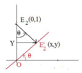 Case 1b: projection of special point E2(0,1) onto the line making image point E'2
Let E2(0,1) denote the special point, and let E'2 be the projected image. Since the coordinates of this projected image are to be found, let them be (x.y) where x and y are unknowns whose values are to be found. Note: x and y are not those found in case 1a.
Drop a perpendicular from E'2 to the y-axis making the point Y there. Notice that
|OE2| =1 and |OY| = y As a result there are two right triangles
right triangle E2E'2O and right triangle E2YE'2
Let θ (black) = angle YE2E'2.
Angle E'2OE2 is in both of the triangles and therefore is equal to both
90° -- θ and 90° -- θ
Therefore θ = θ.
The coordinates of this projected image E'2 are to be found. Let x and y be the unknown coordinates. So E'2(x,y) is the complete representation of the image.
In right triangle E2YE'2,
tan θ = |YE1| / |E'1X| = x / (1 -- y)
Therefore,
(#) x = (1 -- y)tan θ
Since line passes through the origin, y/x - slope = tan θ. So
(**) y = x tan θ
Substitute the equivalent for y in (**) for y in (#) to get
x = tan θ -- x tan2 θ
This means
x sec2θ = tan θ
Solving for x,
x = tan θ / (sec θ sec θ)
Therefore
x = sin θ cos θ
To get the value for y, substitute this value for x in (**):
y = x tan θ = cosθ sin θ sin 2 θ
Therefore the image of (0,1) has been found for 0° < θ < 90°:
E'2(sin θ cos θ, sin2θ)
From E'1(cos2θ, sin θ cos θ) and E'2(sin θ cos θ, sin2θ)
(&)
the images of (1,0) and (0,1) are
(cos2θ, sin θ cos θ) and (sin θ cos θ, sin2θ)
This has been proven for 0° < θ < 90°).
----------
Case 2: The line goes from lower right to upper left (90° < θ < 180°)
 Case 2a: projection of special point E1(1,0) onto the line making image point E'1
Let E1(1,0) denote the special point, and let E'1 be the projected image. To find the coordinates of E'1.
Reflect everything about the x-axis. Then the image of line is a line* that goes from lower left to upper right. Let θ* be its inclination angle with the positive x-axis. Then 0° < θ* < 90°. Then case1a can be applied here. Let E*1 be the projected image of the special point E1 onto line*. Then by case 1a,
E*1(cos2 θ*, sin θ* cos θ*)
Now reflect E*1 across the x-axis onto E'1. Then this reflection requires the first coordinate to remain the same, but the second coordinate is negated. Therefore,
E'1(cos2 θ*, - sin θ* cos θ*)
Now angle E'1OE1 is congruent to angle E1OE*1 because of the reflection about the x-axis, and angle E'1OE1 is congruent to angle WOV because they are vertical angles. So angle WOV = θ*. Since the x-axis forms a straight angle,
θ* = 180° -- θ
Therefore,
E'1(cos2 θ*, - sin θ* cos θ*) =
E'1(cos2 (180° -- θ), - sin (180° -- θ) cos (180° -- θ)) =
E'1(cos2θ, sin θ cos θ)
----------
 Case 2b: projection of special point E2(1,0) onto the line making image point E'2
Let E2(1,0) denote the special point, and let E'2 be the projected image. To find the coordinates of E'1.
Reflect everything about the y-axis. Then the image of line is a line* that goes from lower left to upper right. Let θ* be its inclination angle with the positive x-axis. Then 0° < θ* < 90°. Then case1b can be applied here. Let E*2 be the projected image of the special point E2 onto line*. Then by case 1b,
E*2(sin θ* cos θ*, sin2θ*)
Now reflect E*2 across the y-axis onto E'2. Then this reflection requires the second coordinate to remain the same, but the first coordinate is negated. Therefore,
E'2(- sin θ* cos θ*, sin2θ*)
Again
θ* = 180° -- θ
Therefore,
E'2(- sin θ* cos θ*, sin2θ*) =
E'2(- sin (180° -- θ) cos (180° -- θ), sin2 (180° -- θ),) =
E'2(sin θ cos θ, sin2θ,)
A linear transformation L preserves distance if and only if it carries the special vectors onto orthonormal position vectors
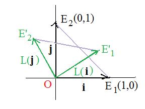 Special vectors are i = OE1 and j = OE2. They are on the sides of triangle OE1E2
If L preserves distance then it carries isosceles right triangle OE1E2 onto congruent triangle OE'1E'2. Then
|OE'1| = 1, |OE'2| = 1, angle E'1OE'2 is a right angle
This means that
|L(i)| = 1, |L(j)| = 1 L(i) * L(j) = 0
This makes images L(i) and L(j) orthonormal position vectors.
Conversely,
Let P and Q be any points. To show that segments L(PQ) and PQ have the same length, that is |L(PQ)| = |PQ|.
Let r = q -- p. Then
PQ = q -- p = r and L(PQ) = L(q -- p) = L(r)
Therefore, to show |L(PQ)| = |PQ| it is sufficient to show |L(r)| = |r|.
Actually it is easier to show |L(r)|2 = |r|2.
r locates some point R. Let (x,y) be the label attached to that point. Then by the distance formula,
|r|2 = x2 + y2
Also
r = (x,y) = x(1,0) + y(0,1) = xi + yj and
L(r) = xL(i) + yL(j)
|L(r)|2
=
L(r) * L(r)
=
(xL(i) + yL(j)) * (xL(i) + yL(j))
=
x2L(i)*L(i) + 2xyL(i) * L(j) + y2L(j)*L(j)
=
x21 + 2xy0 + y21
=
x2 + y2
=
|r|2
=======================================================
Geometric approach to linear transformations
Since these linear universes are sets, there exist functions that carry all the points from a linear universe into a linear universe. These functions will be given some further conditions to become acceptable functions. For example, a function may carry all the points of a line onto a line. It is possible to find a function that carries an entire plane onto a single line. A function that carries a line onto a semi-circle would not be considered acceptable since a semi-circle is not one of the four linear universes. Another condition on acceptable functions is that the origin is carried by them onto the origin. A function that carries an entire linear universe onto a single point (it must be an origin) is called trivial or constant. Such functions are acceptable, but not very interesting.
One of the geometric figures that receives much attention in these discussions is the parallelogram. Only functions that preserve the form of a parallelogram will be acceptable. This means that if points O,P,R,Q are vertices of a parallelogram, then images O,F(P),F(R),F(Q) must also be vertices of a parallelogram. (See adjacent Fig1.) A slight problem occurs if F carries all of the points in the first linear universe onto points of some line. Then the four images are points of a "collapsed parallelogram".
(See adjacent Fig2.). Click here to see a discussion of collapsed parallelograms.
The opposite sides of a parallelogram are parallel. This forces acceptable non-trivial functions to carry parallel lines onto parallel lines. (Assume that any line is parallel to itself.) Such functions are said to "preserve parallelism." There are functions in a higher geometry, called projective geometry, that carry lines onto lines but do not preserve parallelism.
There is another condition that "acceptable functions" must satisfy. Given any two parallel line segments. They may or not be congruent. However, a quotient of their lengths forms a ratio. An acceptable function will carry these parallel segments onto parallel segments preserving the ratio of their lengths. Therefore, if A and B are the end points of the first segment, and C and D are the end points of the second segment, then F(A) and F(B) are the end points of the image of the first segment, and F(C) and F(D) are the end points of the image of the second segment. Then if λ = length AB/lengthCD then also λ = length F(A) F(B)/length F(C) F(D) if F(C) and F(D) are distinct.
It should be emphasized that an acceptable function need not preserve lengths, only the ratio of lengths. It can carry a trapezoid onto a much larger or much smaller trapezoid, but the ratio of lengths of the parallel sides of each trapezoid must be the same. The ratio condition exists only if the segments are parallel. Parallel segments become congruent if the ratio of their lengths = 1.
[2.1] (Acceptable functions) A function is acceptable if it satisfies all of the following conditions:
(a) It carries all of the points of some linear universe onto a linear universe;
(b) It carries the orgin of the first linear universe onto the origin of the second linear universe;
(c) If two line segments are parallel, then it carries them onto parallel line segments, providing they are not points. Furthermore, the ratio of the lengths of the segments in the first linear universe equals the ratio of the lengths of the segments in the second linear universe.
(d) It carries the four vertices of a parallelogram in the first linear universe onto the four vertices of a parallelogram in the second linear universe.
The acceptable functions belong to "linear geometry". If condition (b) is removed, then the functions only belong to "affine geometry."
Some of these conditions are redundant. It is possible to prove (d) from (c).
The use of position vectors makes the discussion shorter and, hopefully, more understandable. Since linear universes contain an origin O, position vectors exist and any point may be located by a position vector: p = OP locates point P in some linear universe. Let F be a function from that linear universe onto a linear universe. Then F carries point P onto some point F(P) in the second linear universe and therefore F(p) = F(OP) = F(O)F(P) = OF(P) is a position vector from O to point F(P) and locates point F(P) in the second linear universe. It will be convenient in discussions to switch between points and their position vectors that locate the points. Therefore, F carries points onto points as well as their position vectors onto position vectors.
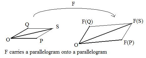 The sum of two position vectors p and q can be done in geometry using a parallelogram. The points Q, O, P are three adjacent vertices of the parallelogram. The fourth point S is located by the position vector OS which is a diagonal of the parallelogram. If F is an acceptable function then F carries the origin onto the origin and parallelograms onto parallelograms. Therefore, points F(Q),O,F(P) are three of the vertices of a parallelogram. The fourth point is is located by a position vector obtained by addition of vectors F(p) and F(q). But the acceptable function carries parallelogram onto parallelogram and therefore carries point S onto this fourth point. Therefore,
F(p) + F(q) = OF(S) = F(OS) = F(p + q)
for any position vectors p and q in the first linear universe
Therefore,
(*) F(p + q) = F(p) + F(q)
This makes F an additive homomorphism. All additive homorphisms carry 0 onto 0. To show this, since 0 = 0 + 0, F(0) = F(0 + 0) = F(0) + F(0). Then subtract F(0) from the equation just found, F(0) = F(0) + F(0) to get 0 = F(0).
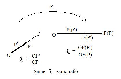 Let P' be any point on the line through distinct points O and P. Suppose O is not between P' and P as shown in the adjacent figure. This makes the ratio λ = OP'/OP non-negative. An acceptable function F carries these collinear points onto collinear points O, F(P') and F(P). Because F preserves ratios of lengths of line segments, λ = OF(P')/OF(P). Therefore for both figures,
OP' = λOP and OF(P') = λOF(P)
In the language of position vectors this translates into
p' = λp and F(p') = λF(p)
Replace p' in this last equation by λp to get
(*) Fλp) = λF(p)
But the discussion has supported this equality only for λ>0. (It is trivially true for λ=0.) Some simple manipulations will show that the equation is true for λ<0 without direct geometric support.
Since F is a homomorphism,
F(λp + (-λ)p) = F(λp) + F((-λ)p)
Therefore,
0 = F(0) = F(λp) + F((-λ)p)
This means that
F(λp) = - F((-λ)p)
But - λ >0 , so from the argument above, F((-λ)p) = (-λ)F(p). Therefore,
F(λp) = -(-λ)F(p)
or
(**) F(λp) = λF(p)
Equations (*) and (**) become necessary conditions that a function F be a linear transformation.
The two diagonals and the line joining the mid points of the parallel sides of a trapezoid are concurrent.
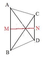
In the adjoining figure is trapezoid ABDC with parallel sides AB and CD, and mid points M and N of those sides respectively. To show that the two diagonals AD and BC and line MN all intersect at some point, say W.
Since M and N are mid points,
(*)
2m = a + b, 2n = c + d
Since AB is parallel to CD, AB = λCD for some real number λ. Hence
b - a = λd - λc
Rearranging,
a - λd = b - λc
Each side of this equation locates a point on the diagonals, which must be W. Therefore,
(1 - λ)w = a - λd = b - λc
Now multiply the second equation in (*) by λ and subtract to get
2m - 2λn = a + b - 2λc - 2λd
= a - 2λc + b - 2λd
= (1 - λ)w + (1 - λ)w
= 2(1 - λ)w
Divide both sides of the equation 2(1 - λ)w = 2m - 2λn to get
(1 - λ)w = m - λn
This shows that point W is also on the intersection of the diagonals AD and BC.
By replacing midpoints with ratios a stronger theorem can be stated: if M and N satisfy the condition that
AM/AB = DN/DC
then diagonals and MN are concurrent. Note that the above theorem is a special case, namely,
AM/AB = 1/2 = DN/DC
Question: is this stronger theorem still true if the ratios AM/AB = DN/DC are greater than 1 or less than 0?
Diagonals and sides of a symmetric trapezoid
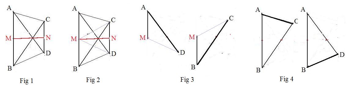 If there exists a perpendicular bisector to the two parallel sides of a trapezoid then the diagonals are congruent and the other sides of the trapezoid are congruent. (Fig 1)
Given trapezoid ABDC and perpendicular bisector MN to parallel sides AB and DC. To prove diagonals AD and Bc are congruent and sides AC and BD are congruent.(Fig 1)
Draw auxilary lines MC and MD. (Fig 2) To prove triangles AMD and BMC are congruent (Fig 3). Also to prove triangles ABC and BAD are congruent.
To prove triangles AMC and BMC are congruent. (Fig 3)
Because line MN is a perpendicular bisector to side BC (Fig 2), the right triangles MNC and MND are congruent. Therefore angle CMN = angle DMN. Also angle AMN = angle BMN.
Then
angle AMD = angle AMN + angle DMN = angle BMN + angle CMN = angle BMC.
Also because the right triangles are congruent, MC = MD.
Since M is the mid point, MA = MB.
This guarantees the congruence of triangles MDA and MCB. Therefore,
AD = BC
To prove triangles ABC and BAD are congruent. (Fig 4)
From the congruence of triangles AMD and BMC (Fig 2), angle BAC = angle ABC. Also AB = BA and from above AD = BC. Therefore triangles ABD and BAC are congruent. Therefore,
AC = BD
The fact that AD, BC and MN are concurrent is proven above, but not used in this proof. However, it can be used to prove sides AC = BD directly.
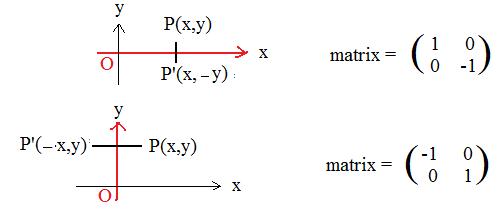
Orthogonal reflection of the plane through a line that passes through the origin; alternate derivation
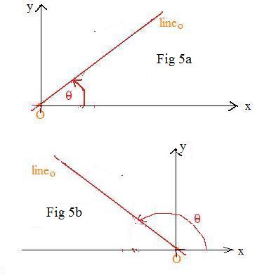 The most convenient algebraic definition of the reflection uses coordinates. Place the axis of reflection lineo in the plane of the xy-axes.(see Fig. 2.) Then lineo makes an inclination angle θ measured counterclockwise from the positive x-axis. The origin and the inclination angle completely determine the axis of reflection. The inclination angle may be restricted to being between 0° and 180° inclusively, and still determine any line through the origin.
If the reflection L about a line through the origin with inclination angle θ carries the point (x,y) onto the image, the formula is:
L(x,y) =
(x cos 2θ + y sin 2θ,
x sin 2θ -- y cos 2θ)
If (x',y') = L(x,y) is the image point then the formula becomes
x' = x cos 2θ + y sin 2θ,
y' = x sin 2θ -- y cos 2θ
The matrix associated with the reflection L is

 Verification for:
Case 1: θ = 0° (axis of reflection = x-axis)
x' = x cos 0° + y sin 0° = x
y' = x sin 0° -- y cos 0° = -- y
L(P) = P': L(x,y) = (x,--y)
Case 2: θ = 90° (axis of reflection = y-axis)
x' = x cos 180° + y sin 180° = -- x
y' = x sin 180° -- y cos 180° = y
L(P) = P': L(x,y) = (--x,y)
(Note: in this discussion, letters in red denote constants that are fixed throughout the discussion, while letters in black denote variables that depend upon the position of point P which may change location. Exceptions: the reflection L, the x-axis and the y-axis which are black.)
P(x,y) is an arbitrary point, and P'(x',y') is its image, where P' = L(P) and (x'y') = L(x,y).
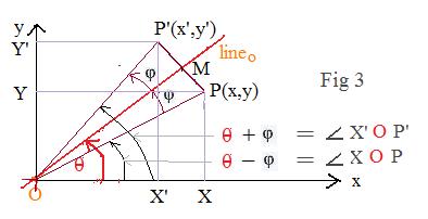 Case 3: 0° < θ < 90°
The terminal side of θ is between the positive x-axis and the positive y-axis.
Drop from P and P' down to the horizontal x-axis to get points X and X'. Then OX = x and OX' = x'. Similarly project P and P' onto the vertical y-axis to get points Y and Y'. Then OY = y and OY' = y.
Let M be the midpoint of segment PP". M is on lineo. Also MP is perpendicular to
OM. Let φ = angle POM. Then in right triangle POM
OP cos φ = OM, OP sin φ = MP
Now focus attention on triangle XOP. Since angle φ is part of angle θ angle XOP = θ -- φ. Since triangle XOP is a right triangle,
x = OX = OP cos (θ -- φ),
y = OY = OP sin (θ -- φ)
Therefore,
(1)
x = OP cos (θ -- φ)
= OP cos θ cos φ + OP sin θ sin φ
= OP cos φ cos θ + OP sin φ sin θ =
= OM cos θ + MP sin θ
Similarly with the y-coordinate:
(2)
y = OP sin (θ -- φ)
= OP sin θ cos φ -- OP cos θ sin φ
= OP cos φ sin θ -- OP sin φ cos θ
= OM sin θ -- MP cos θ
Summarizing,
(3)
x = OM cos θ + MP sin θ,
y = OM sin θ -- MP cos θ
Now solve for OM in terms of x and y. Multiply the first equation in (3) by cos θ and the second equation by sin θ and add the results to get
(4) OM = x cos θ + y sin θ
Next solve for MP in terms of x and y. Multiply the first equation in (*) by sin θ and the second equation by cos θ and add the results to get
(5) MP = x sin θ -- y cos θ
The right triangles MOP' and MOP are congruent. Therefore
φ = angle MOP'
Starting with
x' = OX' = OP' cos (θ + φ)
and with
y' = OY' = OP' sin (θ + φ)
a procedure similar to the above leads to the equations
x' = OM cos θ -- MP' sin θ,
y = OM sin θ + MP' cos θ
But those same congruent right triangles support the statements that
OP' = OP, MP' = MP
Therefore
(6)
x' = OM cos θ -- MP sin θ,
y' = OM sin θ + MP cos θ
Using equations (4) and (3) replacing OM and MP in (6) by their equals produce the equations
(7)
x' = x cos 2θ + y sin 2θ,
y' = x sin 2θ -- y cos 2θ
.
The matrix for this reflection is:
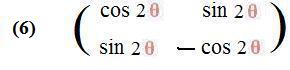
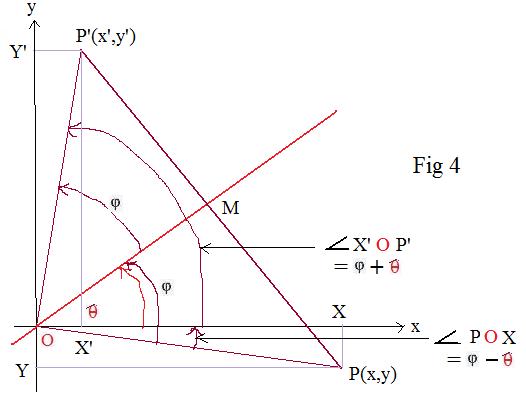 Figure 3 above shows that φ < θ. The adjacent figure 4 shows φ > θ and from the right triangle POX come the equations
x = OX = OP cos(φ -- θ) = OP cos(θ -- φ)
y = -- OY = -- OP sin(φ -- θ) = OP sin(θ -- φ)
Recall from trigonometry that the cosine of the negative of an angle is equal to the cosine of that angle. By convention OY is the (non-negative) length of segment OY, and is never negative. But coordinate y is negative in Fig. 4 because it is below the x-axis. Finally the sine of the negative of an angle is equal to the negative of the sine of that angle.
The computation from now on is the same as that in (1) to (8) above. Therefore (7) and 8 placed here show that the formulas and matrix are true for the point P below the x-axis (but to the right of the y-axis).
Case 4: 90° < θ < 180°.
The terminal side of θ is between the positive y-axis and the negative part of the x-axis.
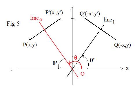 Let P(x,y) be a point and P'(x',y') its image after reflection about lineo. Reflect both points and lineo about the vertical y-axis to get points Q(-x,y) and Q'(-x',y') and line1. It is not difficult to show that Q' is the image of a reflection of Q about line1. Let θ' be the inclination angle of line1. According to (8) the matrix of the reflection (linear transformation) about line1 is
 This means that
(-x',y')t = M (-x,y)t
This is equivalent to a pair of equations
--x' = --x cos 2θ' + y sin 2θ', ; y' = --x sin 2θ' -- ycos 2θ'
It is not difficult to show that θ + θ' = 180° In the above equations, 180° -- θ can replace θ' to get after simplification the equations in (7). This makes the transformation linear and (8) is its associated matrix.
This means that
(-x',y')t = M (-x,y)t
This is equivalent to a pair of equations
--x' = --x cos 2θ' + y sin 2θ', ; y' = --x sin 2θ' -- ycos 2θ'
It is not difficult to show that θ + θ' = 180° In the above equations, 180° -- θ can replace θ' to get after simplification the equations in (7). This makes the transformation linear and (8) is its associated matrix.
In all the diagrams the point P was shown below the axes of reflection. And the image P' was above. Equations (7) correspond to this arrangement. If x and y are solved for in terms of x' and y' the result is
(7')
x = x' cos 2θ + y' sin 2θ,
y = x' sin 2θ -- y' cos 2θ
These equations describe the reflection of P'(x',y') back onto P(x,y). The matrix for this reflection is (8).
This takes care of a point being above the axis of reflection: the same associated matrix appears.
A shorter argument is based on the fact that the matrix in (8) is its own inverse.